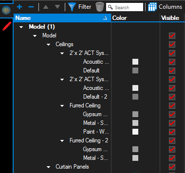
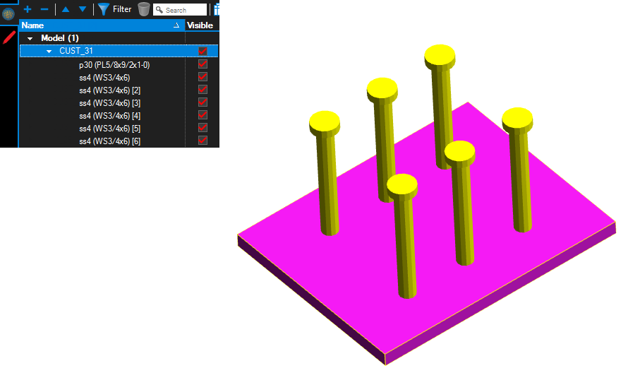
The 3D Model Tree tab toolbar contains many tools for interacting with 3D content.

 Expand All and
  Collapse All: Expands or collapses the entire 3D Model Tree list.
 Previous and
 Next: Moves to the previous or next item in the 3D Model Tree list.
 Filter and
  Clear Filters: Toggles column filters on and off and clears previously applied filters.
 Search: Filters the 3D Model Tree list based on the text entered in the field. Click the X in the field to clear the search term.
 Columns: Selects which columns are shown in the 3D Model Tree list.
 Previous View: Loads the previous view in the View list.
 Next View: Loads the next view in the View list.
 Home: Loads the Default view.
 Model menu: Contains options for affecting the individual parts of the model.
Show All Parts
: Makes visible any part which has been hidden and the sets the transparency as defined in the PDF.
Reset Parts
: Resets parts to their original location. Parts can be transformed (moved and rotated) to other locations. The Reset Parts command quickly resets the parts in the model back to their default location. Reset Parts does not change the visibility of parts.
Fit Model: Resizes the model within the 3D Model window to maximize its size relative to the viewing area.
Set Selection Colors: Calls up the 3D Model Selection Colors dialog box, which enables setting a selected part color and bounding box color, as well as toggling bounding box visibility.
Markup Indicators: Toggles whether to show the Markup Indicators.
Fit to Window: Fits the PDF is the main workspace , maximizing space for the 3D Model.
 Mouse Interaction menu: Determines the mouse behavior when interacting with the 3D model. The options are Rotate, Spin, Pan, Zoom, and Camera. The menu icon displays the currently selected mode.
 Rotate: Moves the camera around the model.
 Spin: Rotates the model around a point that is specified in the model. In most cases Rotate and Spin have very similar behavior. However, Spin may prove more useful on models that have no defined tilt.
 Pan: Moves the model up/down and left/right in the 3D Model window.
 Zoom: Moves the viewpoint in or out to increase the relative size of the model.
 Camera: Rotates the viewpoint from the position of the camera, for an effect similar to tilting one’s head up or down, or rotating it left or right.
 Select: Select parts so they can be moved, rotated, copied or deleted.
The best way to become familiar with these operations is to select the different modes and interact with the 3D model using the mouse.
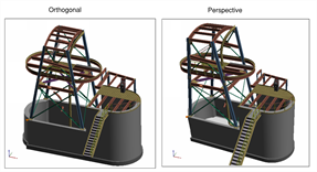
 Perspective: Switches between Orthogonal and Perspective views. The Perspective view takes 3D viewing effects such as foreshortening into consideration, similar to real-world viewing scenarios. Objects closer to the camera view appear larger than objects further away. The orthogonal view keeps the relative size of the objects the same regardless of distance from the viewing (camera) position.

 Lighting menu: Controls the lighting style used to render the model.
 Background Color menu: Controls the color of the background of the 3D Model window.
 Cross Section menu: Shows or hides the cross section plane or section box or aligns the camera perpendicular to the cutting plane. See Cross Sections and Section Boxes for more information about using these tools.
 Transform: Allows you to manipulate selected parts in a 3D model. Selected parts can be moved, rotated, copied and deleted.
 3D Model Tree tab contains powerful tools for interacting with and marking up 3D content. The 3D Model Tree tab can contain a lot of information shown in multiple columns and many users find it easier to view in the bottom panel beside the Markups list. See Getting Around the Revu Interface for more information about moving tabs between the panels.
 Home: Loads the Default view.
 Mouse Interaction menu: Determines the mouse behavior when interacting with the 3D model. The options are Rotate, Spin, Pan, Zoom, and Camera. The menu icon displays the currently selected mode.
 Spin: Rotates the model around a point that is specified in the model. In most cases Rotate and Spin have very similar behavior. However, Spin may prove more useful on models that have no defined tilt.
 Zoom: Moves the viewpoint in or out to increase the relative size of the model.
 Background Color menu: Controls the color of the background of the 3D Model window.

