Cross Section Planes and Boxes
Cross section planes and boxes enable slicing a 3D model view along one of three axes or using a box that can clip along each of the six sides of the view. This is useful for seeing inside a model.
The Cross Section menu is access from the 3D Model Tree panel toolbar. The icon itself changes to reflect the current mode and clicking it will toggle the cross section plane or box on or off, as appropriate, or the following commands can be found in the menu by clicking the arrow immediately to the right of the icon:
 /
/  Show/Hide Cross Section: Toggles the cross section plane on and off.
 /
/  Show/Hide Cross Section Box: Toggles the cross section box on and off.
Align Camera with Cutting Plane: Repositions the camera to be perpendicular with the cross section cutting plane.
The location of the cutting plane and section box can be defined by either direct input or by using the transform controls by selecting the section and dragging the controls.
The cross section transform controls allow for defining the position of a cross section plane or box using the mouse. To access and use the transform controls:
- Select Show Cross Section or Show Section Box from the Cross Section menu, as appropriate.
- Click on the section to select it.
- For a Cross Section: Click and drag one of the three axis lines to move the cross section plane
- Alternatively, click and drag one of the three circles to "tilt" or "rotate" the plane on that axis.
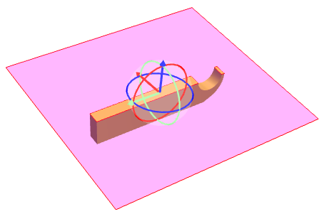
- Alternatively, click and drag one of the three circles to "tilt" or "rotate" the plane on that axis.
-
For a Section Box: Click and drag one of the lines that define the location of any of the six sides of the section box.
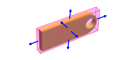
- To reset the section to its default properties, click the Reset button on the
 Properties panel.
The location, appearance, and behavior of the cutting plane and section box can be defined through direct input on the  Properties panel. Go to Window > Panels >
  Properties or press ALT+P to show the
  Properties panel, then toggle the cross section plane or box on and select it in the main workspace. The Position controls appear on the
  Properties panel.
This section contains controls and options that enable slicing the view along one of the three axes or using a box that can clip along each of the six sides of the view.
Slices the view across one of the three axes.
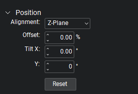
Alignment: Defines the axis along which the cutting plane is aligned.
Offset: Defines the distance from the center of the model at which to place the cutting plane.
Tilt X/Y: Defines the tilt of the plane along the specified axis.
Y/Z: Defines the tilt of the plane along the specified axis.
Note: The tilt parameters are relative to the plane.
Click the Reset button to reset the section to its default properties.
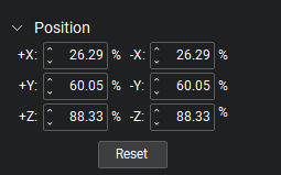
The + and - X, Y and Z values define the location of the size section planes.
Click the Reset button to reset the section to its default properties.
The Appearance and Behavior properties provide additional controls for cross section planes and boxes.
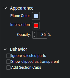
Appearance
Plane Color: Defines color of the section planes.
Intersection: Defines the color shown at the intersection of the part and the section plane.
Opacity: Defines the opacity of the section plane.
Behavior
Ignore selected parts: Selected parts will not be clipped.
Show clipped as transparent: Parts that are intersected by the section plane will appear transparent instead of being clipped. This options is only available for Cross Sections.
Add Section Caps: Uses the part color to show the area of the part that is intersected by the plane.